The incoming solution enters into the Filter Press via a diaphragm pump that is plumbed to the center feed pipe. When the plates are closed, the sludge accumulates in the cavity between the plates. The filtered water exits through the filter cloth and works its way through the stack alternating between the left upper and lower corners and right upper and lower corners, due to the porting differences on the on button and three button plates.
Before the operator can begin filling the filter press, it should be confirmed that the plates are in the 1-3-1-3 button alignment. (This alignment is critical in the air blow-down process.) The unit then needs to be completely closed and all valves should be in the appropriate position. This is accomplished by pushing all them in place by extending the hydraulic cylinder and attaining the recommended PSI. (4000 for automatic and 6500 for manual)
As the filter press fills, it is recommended to begin the feed at 25 PSI and to gradually ramp up the pressure at steady intervals (25, 50, 75) to the maximum pressure of 100 PSI. Upon initial filling of the filter press, the pump will thrust at quick intervals. Conversely, as the press fills, the diaphragm pump will slow down significantly. The easiest way to tell that the press is full is, to listen to the diaphragm pump once it hits 100 PSI. It will dramatically reduce to 30 seconds to 1-minute intervals between thrusts or it may deadhead (stop) altogether. This is your indicator that the cycle is complete. Cycle time can vary from as little as 30 minutes to over 4 hours depending upon what is being filtered. When the filter press is full, all of the chambers will be filled with sludge.
Once the press is full, it is time to operate the Air Blowdown. When the three ball valves on the outlet manifold are closed, and the inlet center feed ball valve is closed, the air that enters the filter press via the small ball valve on the upper left-hand corner of the manifold is forced through the filter press.
Because of the porting denoted by the one button or the three button plate, the air enters into the sludge chamber via the upper left-hand corner of the three button plates and exits via the bottom right-hand corner of the one button plates. This process will push excess water out through the outlet manifold. This process allows for a better cake release and a drier filter cake. Think of this a wringing out the sponge. This is why it is imperative to maintain the 1-3-1-3 alignment of the plates.
Once the Sludge Blowndown Process is complete, the filter press is ready to be opened so that the plates can be cleaned. To open the automatic filter press, reverse the air valve on the automatic hydraulic pump to allow the cylinder to slowly pull open the steel pusher plate. On the smaller manual units, release the ram pressure by simply opening the release valve and the pusher plate will retract via an internal return spring.
Now that the plates are released, pull apart the plates one by one. Most of the sludge will fall into the sludge dumpster on its own. A sludge spatula is provided on new Filter Presses to aide in the sludge removal. Sometimes it is necessary to scrape the residual sludge from the cloths. However, care should be taken to ensure that the cloths are intact and the o-ring and O-ring sealing surfaces are in position and free from obstructions.
Once all plates are clean, the filter press is ready to be closed hydraulically. The three outlet manifold ball valves should be opened, the center feed pipe should be opened and the pump is ready to be switched to the on position. Once the diaphragm pump is reset to 25 PSI, the unit is ready to resume the next fill cycle.

Air operated diaphragm pumps are used with filter presses to pump sludge from the bottom of the sludge holding tank into the filter press. These pumps are ideal because they can handle the slurry which is generally about the consistency of a milkshake.
The diaphragm pump usually starts out slowly and gradually ramps up. Once the pump starts to slow back down, (30-60 seconds between thrusts), it is usually an indicator that the filter press is full. At this point, the feed pump should be turned off and the valves on the filter press closed as the operator prepares to operate the air-blow-down process.
The diaphragm pump can be manually turned up or an Automatic Pump Control system may be added. This starts the pump at 25 psi, then moves up to 50, 75 and finally 100 psi which is standard operating pressure for the pump.
Met-Chem provides diaphragm pumps in the following sizes: 1”, 1.5”, 2” and 3”. The material of construction ranges from cast iron, aluminum, polypro or stainless steel.
With the purchase of a new Met-Chem filter press, Met-Chem can mount your air operated diaphragm pump to the legs of your filter press. This option also includes a flex hose that connects the outlet of the diaphragm pump to the center feed pipe, an air filter, a regulator, and an oiler. We can also provide a mounted diaphragm pump for your existing press.
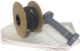 Met-Chem is pleased to offer our spare parts kit which includes our 5 piece center feed pipe assembly, a head, tail, and 2 intermediate filter press cloths, and 100 foot of gasketing material. These are essential items for the operation of the filter press. A cracked pipe, ripped cloth, or torn gasket can happen anytime and having these items in your stock will ensure you will be back up and running in no time.
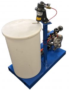
Skid-Mounted Precoat Stations are custom built to work with any filter press (minor changes in the plumbing may be required). The basic precoating system includes a skid-mounted platform with a holding tank, mixer, controls, and a diaphragm pump. The precoat station can also be used as an Acid Wash System to clean filter cloths and maintain high levels of filtration.
The basic precoating operation involves mixing a slurry of filter aid, usually a combination of water and Diatomaceous Earth. The slurry is then pumped into the Filter Press and then recirculated into the holding tank. This process is run until the liquid appears to be clear or until the appropriate depth of precoat is achieved.
Skid-Mounted Precoat Stations can be customized and operated differently depending on the process of your specific application. Contact us for advice on the benefits of these portable skid-mounted systems.
Learn More about a Skid-Mounted Precoat System
When your daily wastewater needs to be collected and treated by a chemical process, a Met-Chem Batch Waste Treatment System can be built to accompany your filter press.
Learn More about a Batch Waste Treatment System
Batch Treatment System are Customized for your Application. Some Features and Options for your system may include:
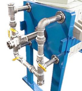 A center feed pipe assembly on a filter press should be able to last many years the same way any other type of plumbing will. However, if the material of the center feed pipe assembly is not strong enough to handle the corrosiveness of the solution running through the press then the center feed pipe assembly can corrode.
For cases of corrosive material or high temperatures, Met-Chem is pleased to offer upgrades from our standard center feed pipe and manifold. We are able to upgrade to CPVC, Carbon Steel, 304 or 316SS Stainless Steel, and Titanium. Met-Chem can also provide additional manifold upgrades such as automatic valves
The center feed pipe is what connects the filter press to the product that needs to be filtered. The center feed pipe assembly consists of five different parts. The first part is the lock nut which fastens on the center feed pipe and connects to the outside of the press. The pipe, which is the second part, goes through the head of the filter and all the way through the head plate of the filter press. The third part of the center feed pipe assembly is a gasket which ensures the assembly is watertight. Next, is the clip nut seat which fastens the assembly to the head plate. This part of the assembly will always stay in place unless you are replacing the assembly or one of its parts. The final part, the cloth clip nut, will be removed often as it is screwed into the cloth clip nut seat after the head cloth is put on the head plate. The cloth clip nut needs to be tightened in order to keep the cloth in place. Met-Chem provides a tool to make this process easier. The Met-Chem Spanner Wrench is a specially designed tool that can be used to loosen and tighten the cloth clip nut when changing the head cloth on a filter press. This tool can be very helpful as the cloth clip, but it has a design that requires a unique tool to tighten and loosen it.
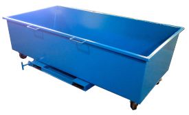 Sludge Dumpsters are used directly under the filter press to catch the sludge that is released from the filter press during cleaning. The dumpster is on casters for easy mobility. They are also equipped with forklift slats for convenient use with a tow motor. The operator can move the dumpster to a roll-off container with the forklift and then pull the release pin for easy emptying. The dumpster can then be snapped back to the upright position and put back under the filter press.
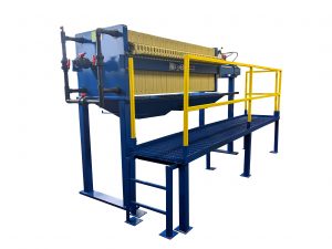
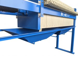
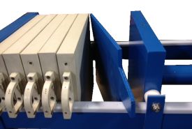 If you produce varying size batches of wastewater and subsequently less sludge, or if the overall volume of waste that is generated at your facility has been reduced, you can still utilize your existing filter press. With the purchase of a backer plate, you can alter the holding capacity of your press to meet your individual batch needs.
A backer plate provides support to the tail plate so that it can be moved anywhere in the plate pack in order to isolate the chambers between the feed end and the tail plate. If you try to use the tail plate in a different position in the plate pack without the backer plate, you run the risk of damaging the chamber of the tail plate.
There are different kinds of backing plates. Some are made of plastic and look much like a standard plate; we prefer to use ~3/8” thick flat stock steel and cut an outline of a plate. This is clearly visible when placed in the stack so that all around know that the filter press is not at full capacity. This steel backing plate is then painted with the same two-part epoxy coating as the frame of the filter press.
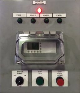 Automatic Pump System Control Panel gradually increases the pump pressure up to 100 PSI for standard units. This allows for even filling of the filter chambers.
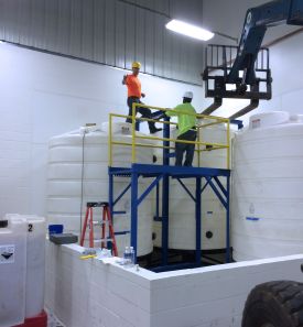 The start-up and installation options are available with all Met-Chem waste treatment equipment. We can provide full support as you get your system up and running. We have installation technicians and technical representatives that we can send to your facility to make sure the system is running as it should based on the engineering and design.
Our services include but are not limited to:
Filling Stage: The Slurry enters and fills the chambers through a feed pump.
Filtration Stage: Once the chambers are filled with the slurry, the pressure from the feed pump will force the liquid filtrate out from the chambers. The Filter Plates and Filter Cloths will capture the solid particles creating sludge.
Air Blowdown Stage: The Air Blowdown Procedure allows the remaining free liquid in the filter press to be purged before the filter chambers are opened. Air is entered through a filtrate port, and the remaining liquid is forced out. This improves cake dryness.
Cake Discharge Stage: Each chamber is opened for cleaning. The sludge is removed and the filter cloths are cleaned if needed.
Met-Chem, Inc.
837 East 79th St.
Cleveland, OH 44103
Phone: (216) 881-7900
Email: info@metchem.com
Copyright © Met-Chem, Inc